Cat5 To Phone Line Wiring Diagram
Doing Your Own Telephone Wiring

Best Cat5 To Rj11 Wiring Diagram Cat5 T568b Wiring Diagram
Cat5 Phone Wiring Diagram Wiring Schematic Diagram
Phone Wiring

Hack Your House Run Both Ethernet And Phone Over Existing

Guides Grounding Wire Diagram 7 Centurylink Nid Wiring Dsl

Click on the image to enlarge and then save it to your computer by right clicking on the image.
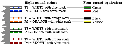
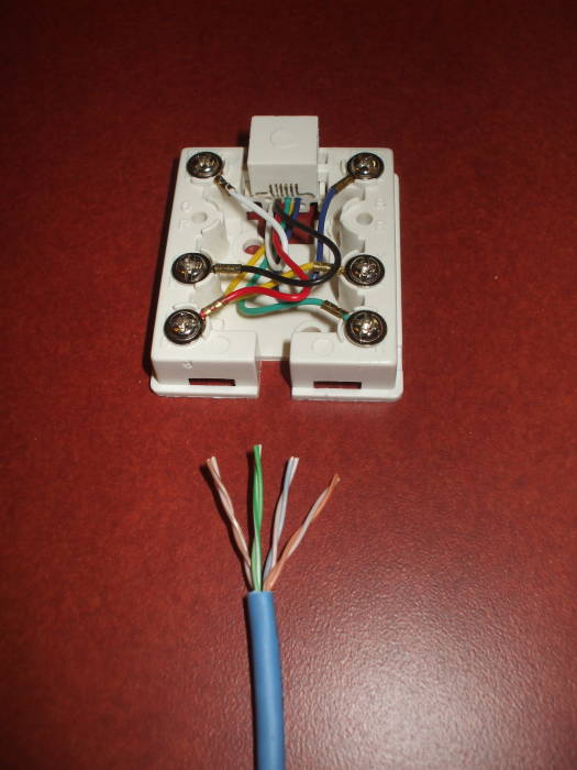
Cat5 to phone line wiring diagram. All of the cat 5 wire ive seen uses the following color coding. Cat5 connectors rj45 have 8 contacts 4 wire pairs. Most phone wire installed in the us. The kind of wire shown above has recently become obsolete.
The phonewireeshown above has now become obsolete. Cat5e socket wiring diagram cat 5 for telephone wire phone. One phone line only requires two of these strands. Assortment of cat5 telephone jack wiring diagram.
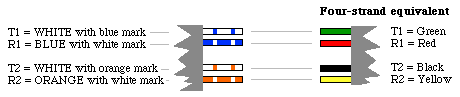
For all new telephone wiring projects you should use cat5 cable. All cat 5 wire ive seen in phone systems use the following color coding. Red and green as in christmas. Only the middle 4 are normally used.
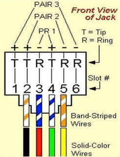
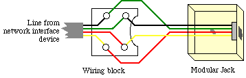
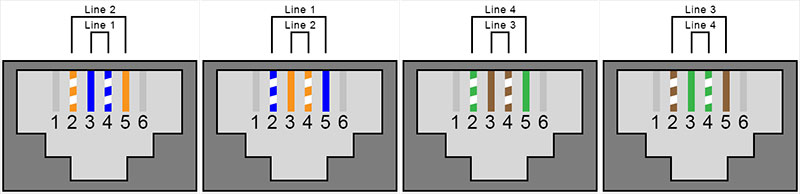
In the vast majority of cases the other two wires go. Some premade phone cables only have the center two wires. Standard telephone jacks rj11 have 4 contacts 2 wire pairs. Otherwise the arrangement will not function as it should be.
Cat5 phone line wiring diagram cat5 phone line wiring diagram every electrical structure is made up of various different pieces. Connect the cat5 pair to the red and green on the standard phone jack. In either case the important point is this. During the second half of the 20th century is of the following kind.
Each part should be set and connected with different parts in specific manner. These cables will be absolutely useless for two line devices. Line 1 is the center pair. Nowadays cat5 cable is commonly used instead of station wire for telephony.
Doing Your Own Telephone Wiring

Cat5 Phone Wiring Diagram Wiring Schematic Diagram

Rj11 Wiring Diagram Using Cat5 Lovely Using Rj11 Cat5 Wiring

Cat5 Phone Line Wiring Diagram Australia Wiring Diagram

Cat5 Phone Wiring Diagram Wiring Schematic Diagram

Cat5 To Phone Jack Cooctolab
How To Install A Dsl Line
Tech Stuff Mixed Lan And Telephone Wiring

Leviton Rj11 Jack Wiring Diagram Wiring Diagram
Doing Your Own Telephone Wiring

How To Distribute Voip Throughout A Home
Rj11 Phone To Rj45 Jack

Cat5e To Rj11 Wiring Diagram Phone Jack Wiring Color Code
Structured Wiring Panel

Rj11 Wiring Diagram Using Cat5 Wiring Diagram And Schematic
