Control Wiring Ladder Diagram
Ladder Diagrams Ladder Logic Electronics Textbook
Ladder Diagram Basics 1

Control Wiring Ladder Diagrams Wiring Diagram

Control Wiring Ladder Diagrams Wiring Diagrams

How To Construct Wiring Diagrams Industrial Controls

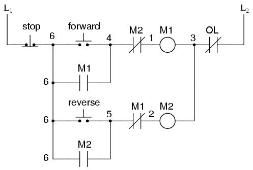
Motor Forward And Reverse Control Circuit Fred In 2019

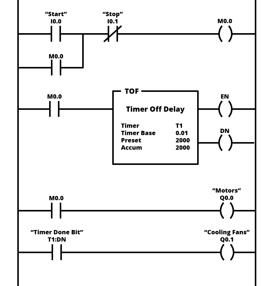
However if you take your time and learn how to convert a basic wiring diagram to a ladder logic plc program it can be an easily achievable task.
Control wiring ladder diagram. Residential wire pro for electrical floor plans with pdf import. Electrical ladder drawings are still one of the common and reliable tools used to troubleshoot equipment when it fails. The process composed of three steps. A wiring diagram shown in figure 1 is an electrical print that shows connections of all components in a piece of equipment.
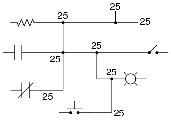
Sorry for the interruption. A filling a tank to a predetermined level b agitating the liquid for 30 minutes c draining the tank for use in another part of process does the ladder logic schematic that follows perform. Wiring diagrams tend to show a close representation of the interior position of electrical components in a control cabinet andor circuit. Ladder diagrams will be referred to as schematic diagrams or simply schematics.
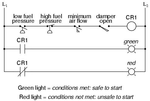
We have been receiving a large volume of requests from your network. With ladder diagrams no attempt is made to show the actual physical locations and the emphasis is on clearly showing how the control is exercised. It is called ladder because the symbols that are used to represent the components in the system have been placed on the rungs of a ladder. As with any good troubleshooting tool one must be familiar with its basic features to make the most of the diagram in the field.
They are called ladder diagrams because they resemble a ladder with two vertical rails supply power and as many rungs horizontal lines as there are control circuits to represent. Ladder diagram basics 6 fwd rev contactor for 3 phase motor. Electrical software for designing teaching testing and printing electrical ladder diagrams. Constructor for ladder diagrams.
Electrical floor plan motor control training and plc training software as well. To continue with your youtube experience please fill out the form below. Upgrading a machine to plc control may seem like a daunting task. This video will walk you through the physical wiring of a 3 wire control circuit for a 3 phase motor starter.
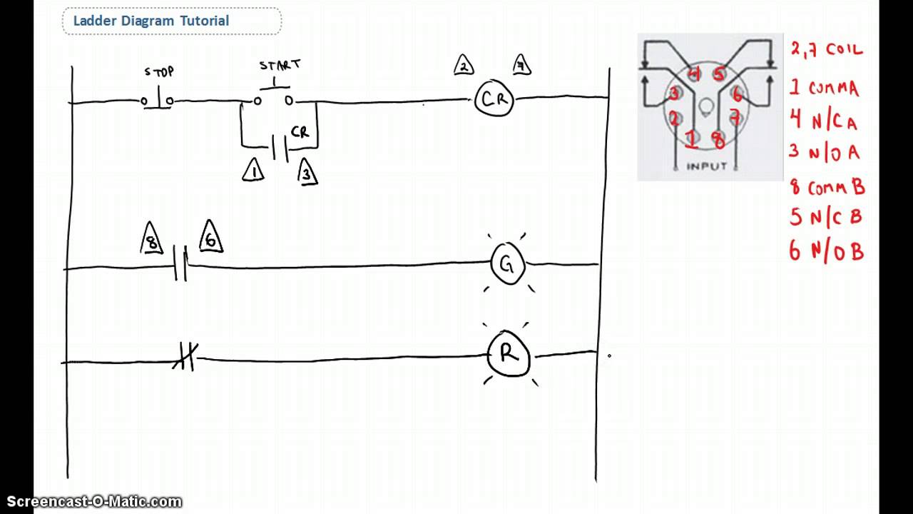
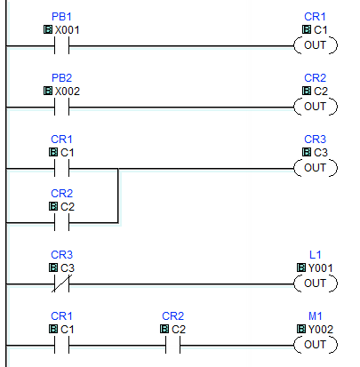
Figure 2 see below shows an example of a ladder diagram for a circuit that is used to start and stop a motor using push buttons. It is the most common type of wiring diagrams. Sometimes wire diagrams can closely represent a picture.

Plc Program For Bottle Filling Ladder Logic Engineering In

Ladder Diagram Basics 3 2 Wire 3 Wire Motor Control Circuit
Lessons In Electric Circuits Volume Iv Digital Chapter 6

Ladder Logic

Ac Motor Control Circuits Worksheet Ac Electric Circuits
Ladder Logic Examples And Plc Programming Examples

Basic Plc Layout

Facility Electrical Control Circuits Wiki Odesie By Tech
Ladder Logic Tutorial With Ladder Logic Symbols Diagrams
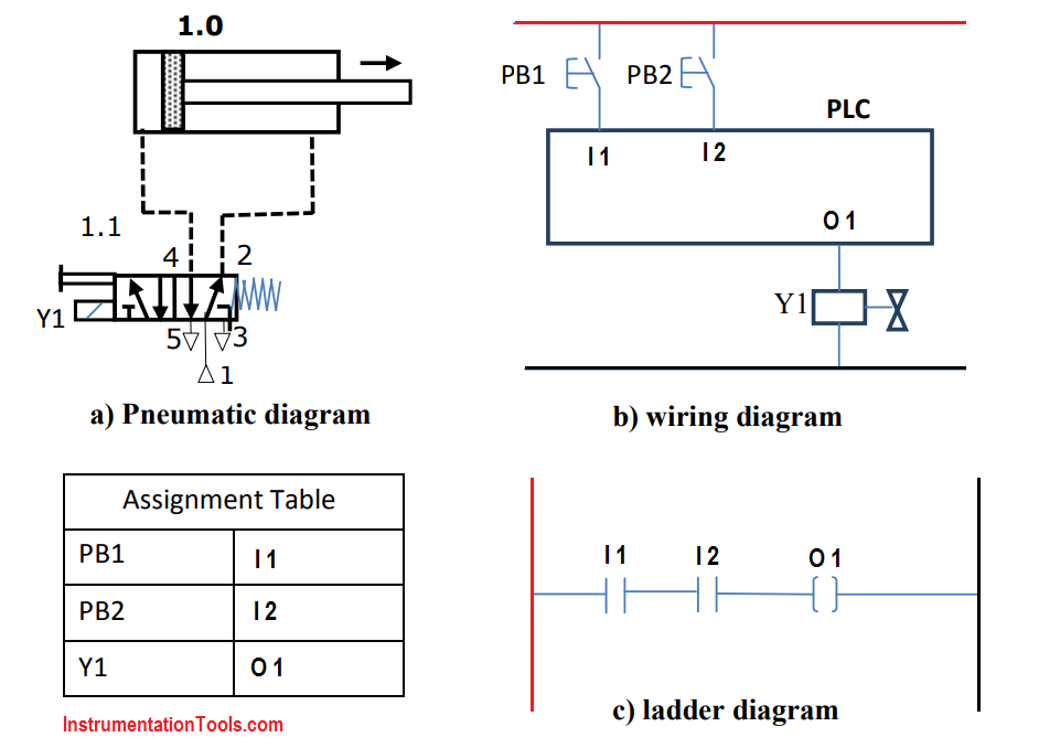
Plc Pneumatic Circuit Control Plc Programming Pneumatic System
Ladder Logic

Ac Motor Control Circuits Worksheet Ac Electric Circuits

1st Sand Play New Milestone Ladder Climbing Jremembrance
What Is Industrial Application Of Plc With Ladder Diagram
Typical Circuit Diagram Of Star Delta Starter Plc Plc
