Lennox Hp26 Wiring Diagram

I Have A Lennox Hp26 036 7p Heat Pump In Cooling Mode The
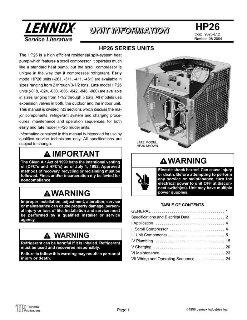
Lennox Hp26 Manualzz Com

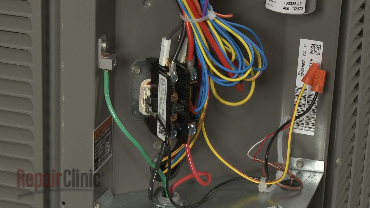
Oops Lennox Hp26 36 Contactor Wiring Connection

Need Wiring Diagram For Lennox 84w88 Installation System Is

32 Wiring Diagram For Electric Furnace Wiring Diagram

New Contactum Contactor Wiring Diagram Diagramspros Com

A wiring diagram is a streamlined traditional photographic depiction of an electrical circuit.
Lennox hp26 wiring diagram. Weve made it easy for you to find the resources you need including product brochures and owners manuals. The hp26 is not equipped with an internal line voltage to 24v transformer. The lennox icomfort touch thermostat must be used in communicating application in nonicomfort applications the lennox comfortsense 7000 thermostat may be used as well as other noncommunicating thermostats. In all cases setup is critical to ensure proper system operation.
Refer to unit wiring diagram. Note a complete unit wiring diagram is located in. It shows the components of the circuit as simplified forms and also the power and also signal connections between the devices. View download of more than 5227 lennox pdf user manuals service manuals operating guides.
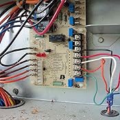
Hp26 field wiring diagram figure 5. Find lennox commercial hvac product service manuals installation guides engineering handbooks application and design guidelines. A single pole contactor is used in early model hp26 units. Collection of lennox wiring diagram.
Improper installation adjustment alteration service or maintenance can cause property damage person al injury or loss of life. 2002 lennox industries inc. Click on your model number below to view the service manual for your unit. 2004 lennox industries inc.
Installation and service must. Viiwiring diagrams and operation sequence. Refer to figure 5 for high voltage field wiring diagram. Refer to the furnace or blower coil installation instructions for additional wiring application diagrams and refer to unit.
Page 6 r c w1 y1 o g r w1 w2 w3 reversing valve outdoor unit and blower unit thermostat designations. Air conditioner user manuals operating guides specifications. Simply narrow your search using the options below. Page 15 the unit wiring diagrams have been revised to reflect the code 12 outdoor temperature sensor this code indicates a problem with the operation of the out changes for the hp21 4 5 tsc 6 and are shown in section door temperature sensor.
Field wiring examples for nonicomfort applications begin. See wiring diagram for spe. Code 12 is stored. Single pole and double pole contactors are used in late model hp26 units.

Lennox Hvac Owners Servicers Community Forum

I Have A Lennox Hp26 036 7p Heat Pump In Cooling Mode The
Lennox 84w88 Heat Pump Defrost Control Board Genuine Original Equipment Manufacturer Oem Part
Lennox Condensing Unit Contactor Replacement 10f73

Amazing Carrier Fv4cnb006 Rent Plot Magnificent Espresso
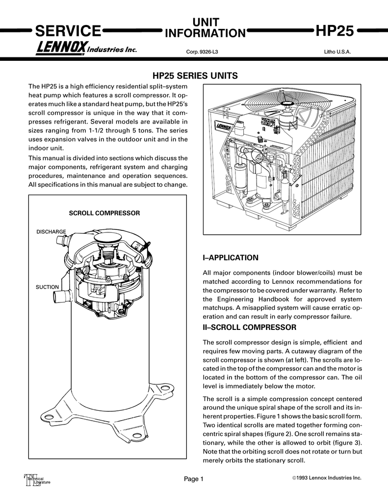
Hp25 Series Units Manualzz Com

How To Fixing My Lennox Air Conditioner Fan Motor Not Working
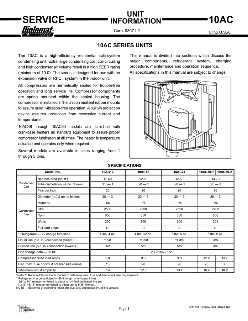
10ac Series Manualzz Com

Lennox Heat Pump Defroster Board Model Hp26 261 3p My

51h75 Lennox Fan Motor

Lennox Air Conditioner Condensing Unit Run Capacitor 12788

Suzuki Vitara Ac Wiring Diagram Auto Electrical Wiring Diagram

Lennox 84w88 Heat Pump Defrost Control Board Genuine Original Equipment Manufacturer Oem Part
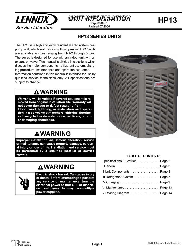
Hp13 Series Manualzz Com

Dual Fuel Hvac Wiring Diagram Wiring Diagram Website Dual
