Motor Starter Diagram Single Phase
Single Phase Starter Connections

Single Phase Motor Control Wiring Diagram Electrical

Single Phase Submersible Pump Starter Wiring Diagram Gooddy
Wiring A Single Phase Motor Through A 3 Phase Contactor How
What Is Direct Online Starter Dol Working Principle

Single Phase Motor Wiring With Contactor Diagram In 2019

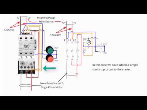
A single phase motor starter wiring diagram is shown in the below figure.
Motor starter diagram single phase. Therefore reversing of single phase motors is not covered here. Merely ignore the control wiring in red. The above diagram is a complete method of single phase motor wiring with circuit breaker and contactor. Another method is the capacitor start induction run motors.
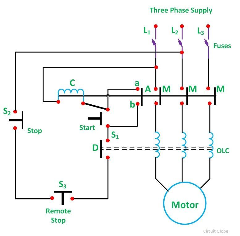
One often used method is the split phase motors. Soft start of induction motor by acpwm in this drive the load is connected in series with the input terminals of the bridge rectifier and its output terminals are connected to the pwm controlled power mosfet igbt or bipolar or power transistor. A wiring diagram is a simplified traditional photographic representation of an electric circuit. Therefore wiring a reversing starter for single phase operation is possible but can only be advised for those who fully understand the wiring techniques of their specific single phase motors and have the knowledge and experience to work out how to apply that to the reversing starter.
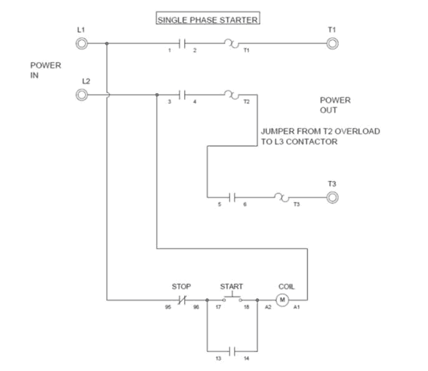
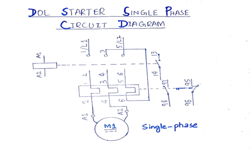
Diagram explanation of how a capacitor is used to start a single phase motor the single phase induction motor can be made to be self starting in numerous ways. In the above one phase motor wiring i first connect a 2 pole circuit breaker and after that i connect the supply to motor starter and then i do cont actor coil wiring with normally close push button switch and normally open push button switch and in last i do connection between capacitor. Single phase motor starters are not commonly available since this is a rare case and with a little bit of know how a 3 phase motor starter can easily be wired for single phase power. The start and stop circuits could alternatively be controlled using a plc.
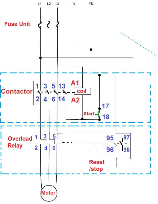
It reveals the parts of the circuit as simplified shapes and the power and signal links between the gadgets. Single phase motor starter wiring diagram collection of single phase motor starter wiring diagram. It uses a contactor an overload relay one auxiliary contact block a normally open start pushbutton a normally closed stop pushbutton and a power supply with a fuse. Full voltage single phase motors this diagram is for single phase motor control.

Power Circuit Of A Single 1 Phase Direct On Line Dol

Single Phase Motor Contactor Wiring Diagram Elec Eng World
What Is Direct On Line Starter Its Theory Of Starting

Ac Motor Control Circuits Worksheet Ac Electric Circuits
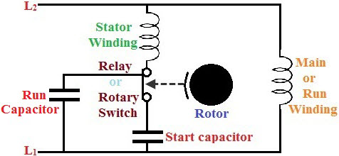
Starting Methods Of Single Phase Motor Circuits With Protection

How Do I Connect A Direct On Line Dol Starter To A Single

Dol Starter Circuit Diagram Wiring Single Phase For Motor

Aim Manual Page 54 Single Phase Motors And Controls

Start Stop Station Wiring Diagram Basic Circuit Onan Switch

Reverse Motor Starters
Starting Methods Of Single Phase Motor Circuits With Protection
Direct Online Starter Dol Starter Working Principle

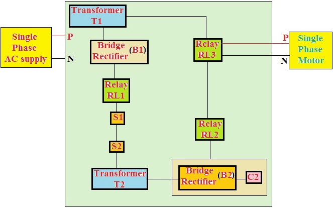
Single Phase Submersible Motor Starter Wiring Diagram

Single Phase Starter Wiring Diagram Bcberhampur Org
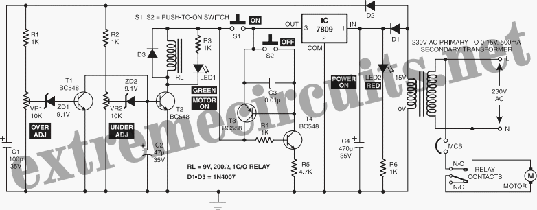
Electronic Motor Starter Circuit Diagram
