Rtd Pt100 4 Wire Wiring Diagram

Connection In 4 Wire Resistance And 4 Wire Rtd Sensor
2 3 And 4 Wire Rtds What Is The Difference Omega
Wiring For Rtd Configurations

4 Wire Rtd Temperature Sensor Rtd Resistance Temperature
2 3 And 4 Wire Rtds What Is The Difference Omega

4 Wire Rtd Temperature Sensor Rtd Resistance Temperature
It reveals the components of the circuit as streamlined shapes as well as the power and also signal links in between the gadgets.
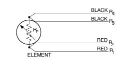
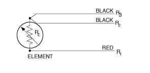
Rtd pt100 4 wire wiring diagram. Microsoft powerpoint 2 3 4 wire rtd measurementppt. In this circuit there are three leads coming from the rtd instead of two. Rtds resistance temperature detectors are offered with 2 3 or 4 lead configuration. What is an rtd rtd types uses and more by jms southeast.
Sor resistance temperature detector rtd proflow systems. It shows the components of the circuit as streamlined shapes and also the power and also signal links between the gadgets. Properties wiring diagrams characteristics and technical specifications. A wiring diagram is a streamlined conventional photographic representation of an electric circuit.
For example heres the approximate resistances of a 4 wire pt100 rtd at 0 0 c for a pt1000 the middle resistance would be 1002 w rather. Assortment of rtd pt100 3 wire wiring diagram. Rtd pt100 3 wire wiring diagram gallery rtd sensors 2 3 4 wire rtd sensors resistance temperature detectors. 4 wire rtd wiring diagram.
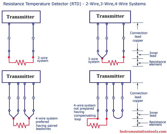
Variety of 4 wire rtd wiring diagram. Idac generates the sensor excitation and the reference voltage. A wiring diagram is a streamlined conventional pictorial depiction of an electric circuit. 2 lead constructions result in leadwire resistance getting added to the element resistance.
Noise and drift of the ref voltage are correlated and. It reveals the components of the circuit as streamlined shapes and the power and also signal connections between the devices. A wiring diagram is a simplified traditional photographic representation of an electrical circuit. Assortment of 4 wire rtd wiring diagram.
Collection of 4 wire rtd wiring diagram. When connected to the amplifier the smart amp will measure the voltage across the rtd and also across the wire pairs. A wiring diagram is a streamlined standard photographic depiction of an electrical circuit. 3 wire rtd wiring diagram awesome rtd sensor temperature ppt video.
Each wire is maybe 1 w of resistance. Difference between 2 wire rtd 3 wire rtd and 4 wire rtds. Analog input module ai 4xrtdtc 2 3 4 wire hf 6es7134 6jd00 0ca1 manual 092018 a5e03573289 ae preface guide to documentation 1 product overview 2 wiring 3. L1 and l3 carry the measuring current while l2 acts only as a potential lead.
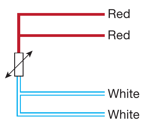
Each side of the rtd has two wires attached. 2 3 4 wire rdt pt100 to pt1000temperature measurement. It shows the elements of the circuit as simplified forms and also the power and also signal links between the devices.

4 Wire Rtd Evolution Sensors And Controls
4 Wire Rtd Wiring A 4 Wire Rtd
Difference Between 2 Wire Rtd 3 Wire Rtd And 4 Wire Rtd S
Connecting 2 3 And 4 Wire Rtds To My Data Acquisition Card

What Is An Rtd Rtd Types Uses And More By Jms Southeast

Lead Compensation Techniques For Rtds
Help Me Understand This 4 Wire Rtd Circuit Electrical
Difference Between 2 Wire Rtd 3 Wire Rtd And 4 Wire Rtd S
Connecting 2 3 And 4 Wire Rtds To My Data Acquisition Card
What Is Actual Working Of 2 Wire 3 Wire And 4 Wire Typs Of

Resistance Temperature Detector Rtd Working Types 2 3 And

Crocsee Rtd Pt100 Temperature Sensor Probe 3 Wires 2m Cable Thermocouple 58 572 F 50 300 C 1 2 Npt Thread
Rtd Amplifier Circuit Measuring Rtds Connecting Rtd To
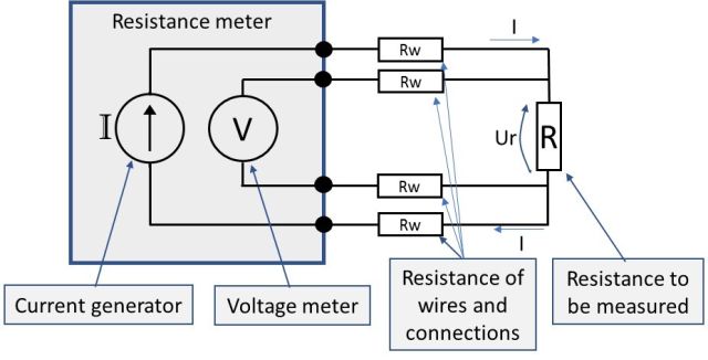
Resistance Measurement 2 3 Or 4 Wire Connection How Does
.jpg)
Resistance Temperature Detector Rtd Principle Of
