Wiring Diagram For 110v Schematic
110v Schematic Wiring Wiring Diagram
Need Wiring Diagram Verification Terry Love Plumbing

110v Gfci Schematic Wiring Diagram Wiring Diagram
Wrg 5047 Wiring Diagram For 110v Schematic

110v Schematic Wiring In Series Wiring Library

110v Schematic Wiring Wiring Diagram

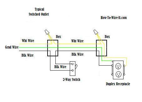
Easy to understand light switch wiring fully explained light switch wiring with diagrams and pictures with step by step instructions to guide you.
Wiring diagram for 110v schematic. It reveals the elements of the circuit as simplified forms and also the power as well as signal links between the tools. Hot neutral and ground. With these diagrams below it will take the guess work out of wiring. Take a closer look at a 3 way switch wiring diagram.
3 way switch wiring diagram. 220v wiring by. With this wiring both the black and white wires are used to carry 120 volts each and the white wire is wrapped with electrical tape to label it hot. A wiring diagram is a simplified traditional pictorial depiction of an electric circuit.
Wiring diagram for late model harbor freight mini lathe with illuminated rocker power switch and safety interlock circuit. This might seem intimidating but it does not have to be. Wiring diagram for late model mini mill with red and yellow emergency stop switch. A typical 110v wiring schematic requires three different wires.
Wiring a 20 amp 240 volt appliance receptacle. With 220v wiring both three and four wire setups are possible. The red and black wires in 220v setups each carry 110v and the green wire is the ground. With four wire setups there is a white wire which is called the neutral.
It shows the components of the circuit as simplified shapes and also the power and also signal links in between the tools. The outlet should be wired to a dedicated 20 amp240 volt circuit breaker in the service panel using 122 awg cable. Autozone repair guide for your chassis electrical wiring diagrams wiring diagrams. This outlet is commonly used for a heavy load such as a large air conditioner.
Understanding the basic light switch for home electrical wiring. Pick the diagram that is most like the scenario you are in and see if you can wire your switch. Wiring diagram for standard micro mark 7x14 mini lathe. A wiring diagram is a streamlined conventional photographic depiction of an electrical circuit.

220v To 110v Wiring Diagram Wiring Diagram

110v Schematic Wiring Multiple Schematics Wiring Schematic
Wall Schematic Wiring Diagram 110v Electrical Wiring Library

Electrical Wall Schematic Wiring Diagram Wiring Diagram
110 Receptacle Wiring Wiring Schematic Diagram

110v 14v 5v Smps Detailed Diagrams With Illustrations
Electrical Wall Schematic Wiring Diagram Wiring Diagram

110v 220v Switch Wiring Diagram Wiring Diagram
What Are The Methods To Convert 220v To 110v With Out Tif

Wrg 5624 Wall Schematic Wiring Diagram 110v Electrical

Three Way Wiring Diagram 110v Wiring Schematic Diagram

How To Wire A Simple 120v Electrical Circuit With Pictures

Wiring A 110 Schematic Wiring Library

Wiring Diagrams

110 Receptacle Wiring Wiring Schematic Diagram
